Overview
There are specific situations like Merges and Acquisitions (M&A) where two companies need to talk to each other but there is address overlap. In some cases, the source and the destination IP address is different which is another use case, and it is easier to solve but still you must enable Network Address Translation (NAT) within the network to avoid any IP address conflict.
The purpose of this tech note is to guide you how to configure NAT when the source and destination IP address is the same. In this case you need to enable Source NAT (SNAT) as well as Destination NAT (DNAT) for the traffic to flow end to end. Also, these functions need to be enabled in separate places of the network depending on where the traffic is initiated from.
For the purpose of this tech note, we assume the reader is familiar with the Aviatrix concepts, networking, NAT functionality, and native cloud constructs.
Introduction
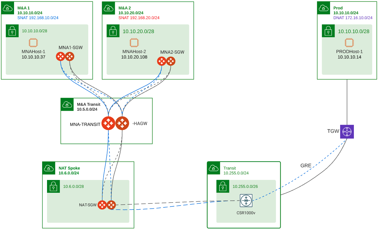
The diagram below depicts the scenario that I will use on this tech note to explain the process and how to configure it. The main use case is to have the host in M&A1 (MNAHost-1) communicate with host in the PROD environment (PRODHost-1). This design allows you to add additional M&As like M&A 2 which might have overlap IP addresses with other M&As or other production environments.
Within Aviatrix the SNAT and DNAT function take place at different times when the packet flows through the gateway. The picture below shows this process.

Using the picture above if we want to send traffic from MNAHost-1 to PRODhost-1 this is how the NAT functions will be implemented

Using the picture above, the NAT function is executed correctly but because the source IP and the destination IP are within the same subnet, then when the gateway delivers the packet it sends it back to Eth0 as it is directly connected to it, so the packet never leaves the gateway. For this reason, in this use case, we must split the SNAT and DNAT function in different gateways. If you look at the overall design, the NAT function will be split between MNA1-SGW and NAT-SGW.
Routing – From the routing point of view, MNA1-GWY advertises to the Aviatrix transit only its virtual prefix 192.168.10.0/24. This helps to keep the different M&As separated in case they also have overlapping IP addresses. This is done from the controller. The NAT VPC in this exercise is configure for 10.6.0.0/24 but it could be configured for a different CIDR. The NAT-GWY is advertising its virtual prefix 172.16.0.0/16 but it was the real CIDR then it could advertise it.
1) Expand Multi-Cloud Transit, select List, select Spoke submenu on top of the list, Select the gateway you want to make this change on
2) Select Customize Spoke Advertised VPC CIDRs from the Actions menu
Type the virtual prefix to advertise. For example, for MNA1 we have 192.168.10.0/24. What you enter on this field is the only prefix(s) advertised by the gateway into the transit. Basically, it overrides what is connected to the gateway. If you want to advertise more prefixes, you can separate them by coma.

The routing from the Site to Cloud (S2C) in the NAT-GWY to the CSR1000v is static and the remote prefix for the tunnel is 10.0.0.0/8 while the CSR1000v have static routes for 192.168.10.0/24 and 192.168.20.0/24 pointing to both tunnels.
Note: The NAT rules specified in this tech note are specific to this exercise. You can customize them accordingly to your case and be more general or specific.
In this tech note I will demonstrate the NAT configuration for these two traffic flows:
1) Traffic initiated from M&A 1 into Production
2) Traffic initiated from Production into M&A 1
Traffic Initiated from M&A 1 into Production
For this flow, the real IP address of MNAHost-1 is 10.10.10.37 (source) and the real IP address of PRODHost-1 is 10.10.10.14 (destination). The source and destination IP addresses overlap within the same 10.10.10.0/24 subnet. For this reason, we are going to use/define a virtual IP address for PRODHost-1 as 172.16.10.14. Here is the detail diagram for this flow.
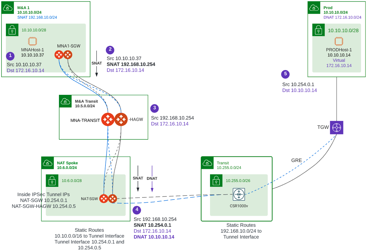
1) SNAT Configuration on MNA1-SGW – In this gateway perform SNAT because the source IP address conflicts with the real destination IP address. Configure SNAT to a virtual IP address 192.168.10.254 which is defined on MNA1-SGW.
- In the controller click Gateways, from the list select MNA1-SGW, click EDIT
- Under the Source NAT section, select Customized SNAT, click ADD NEW and enter the following rule
- DST CIDR – 172.16.0.0/16
- CONNECTION – Select your transit
- SNAT IPS – 192.168.10.254 – You need to add a similar rule on MNA1-SGW-HAGW which is the HA gateway for MNA1-GWY as SNAT rules are not sync between the gateways. For the MNA1-SGW-HAGW gateway use 192.168.10.253. A different IP address is used for each gateway, so traffic returns to the correct gateway.
- Click Save
- Click Update
- Your rule should look like this on each gateway respectively

2) DNAT Configuration on NAT-SGW – In this gateway perform DNAT to convert the destination virtual IP address (172.16.10.14) into the real IP address 10.10.10.14.
- In the controller click Gateways, from the list select NAT-SGW, click EDIT
- Under the Destination NAT section, check Add/Edit DNAT
- Make sure the Sync to HA Gateway is checked
- Click ADD NEW and enter the following rule
- DST CIDR – 172.16.10.14/32 – this is the virtual IP address that we use when initiating our ping
- CONNECTION – Transit
- MARK – 102 – This is just a number to reference this policy, make sure you enter a number as you also have to perform SNAT on this gateway for the same flow
- DNAT IPS – 10.10.10.14 – this is the real IP address of the destination device
- Click Save
- Click Update
- Your rule should look like this, no need to configure on NAT-SGW-HAGW because the two gateways will sync this configuration

3) SNAT Configuration on NAT-SGW – Perform SNAT as well to make sure the return traffic returns through the same gateway performing the DNAT otherwise traffic will be asynchronous and will not make back to the source
- In the controller click Gateways, from the list select NAT-SGW, click EDIT
- Under the Source NAT section, select Customized SNAT, click ADD NEW and enter the following rule
- CONNECTION – Select the site2cloud tunnel to the CSR1000v
- MARK – 102 – This is the same Mark number used in step 2. Mark basically is a reference to traffic that you included in another policy. So instead of defining source and destination and other parameters, you save time by just referencing that policy via a number
- SNAT IPS – Here we are going to use the Inside IPSec tunnel IP address defined to the CSR1000v. In our exercise it is 10.254.0.1 for NAT-GWY and 10.254.0.5 for NAT-GWY-HAGW. Remember that for SNAT you need to perform similar configuration policy on the NAT-GWY-HAGW
- Click Save
- Click Update
- Your rule should look like this on each gateway respectively

4) Test – Perform a ping test, as you can see below our ping from 10.10.10.37 (MNAHost-1) to 172.16.10.14 (PRODHost-1 10.10.10.14) works

Traffic Initiated from Production into M&A 1
For this flow, the real IP address of PRODHost-1 is 10.10.10.14 (source) and the real IP address of MNAHost-1 is 10.10.10.37 (destination). The source and destination IP addresses overlap within the same 10.10.10.0/24 subnet. For this reason, we are going to use/define a virtual IP address for MNAHost-1 as 192.168.10.37. Here is the detail diagram for this flow.
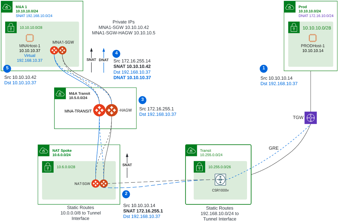
1) SNAT Configuration on NAT-SGW – In this gateway perform SNAT because the source IP address conflicts with the real destination IP address. Configure SNAT to a virtual IP address 172.16.255.1 or to the private of the gateways if the VPC was address with CIDR that will not conflict with the network.
- In the controller click Gateways, from the list select NAT-SGW, click EDIT
- Under the Source NAT section, click ADD NEW and enter the following rule
- DST CIDR – 192.168.10.0/24
- CONNECTION – Select your transit
- SNAT IPS – 172.16.255.1 – You need to add a similar rule on NAT-SGW-HAGW as SNAT rules are not sync between the gateways. For the NAT-SGW-HAGW gateway use 172.16.255.2
- Click Save
- Click Update
- Your rule should look like this on each gateway respectively

2) DNAT Configuration on MNA1-SGW – In this gateway perform DNAT to convert the destination virtual IP address (192.168.10.37) into the real IP address 10.10.10.37.
- In the controller click Gateways, from the list select MNA1-SGW, click EDIT
- Under the Destination NAT section, check Add/Edit DNAT
- Make sure the Sync to HA Gateway is checked
- Click ADD NEW and enter the following rule
- DST CIDR – 192.168.10.37/32 – this is the virtual IP address that we use when initiating our ping
- PROTOCOL – All
- CONNECTION – Transit
- MARK – 101 – This is just a number to reference this policy, make sure you enter a number as you will perform SNAT on this gateway for the same flow
- DNAT IPS – 10.10.10.37 – this is the real IP address of the destination device
- Click Save
- Click Update
- Your rule should look like this, no need to configure MNA1-SGW-HAGW because the two gateways will sync

3) SNAT Configuration on MNA1-SGW – In this gateway perform SNAT as well to make sure the return traffic returns through the gateway performing the DNAT otherwise traffic will not make back to the source
- In the controller click Gateways, from the list select NAT-SGW, click EDIT
- Under the Source NAT section, click ADD NEW and enter the following rule
- INTERFACE – eth0
- CONNECTION – None
- MARK – 101 – This is the same Mark number used in step 2. Mark basically is a reference to traffic that you included in another policy. So instead of defining source and destination and other parameters, you save time by just referencing that policy via a number
- SNAT IPS – Here we are going to use the private IP address of the gateways. In our exercise it is 10.10.10.42 for MNA1-GWY and 10.10.10.10.54 for MNA1-GWY-HAGW. Remember that for SNAT you need to perform similar policy on the MNA1-GWY-HAGW gateway.
- Click Save
- Click Update
- Your rule should look like this on each gateway respectively

4) Test – Perform a ping test, as you can see below our ping from 10.10.10.14 (PRODHost-1) to 192.168.10.37 (MNAHost-1 10.10.10.37) works

Verification
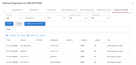
During the deployment, packet capture on any of the gateways can be done from the Controller or CoPilot to help troubleshoot the environment and make sure that the NAT function is implemented accordingly in the different points of the network.
Here is an example of a packet capture on MNA1-GWY from CoPilot. This is for traffic from MNA1 to PROD. Here you can see how 10.10.10.37 is SNAT into 192.168.10.254 (second row).
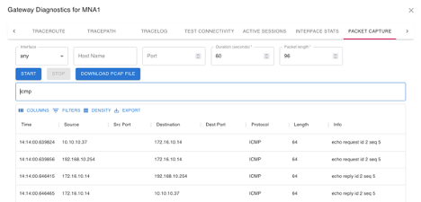
Here is the packet capture for the same flow on NAT-GWY. Here you can see how 192.168.10.254 is SNAT into 10.254.0.1 and 172.16.10.14 is DNAT to 10.10.10.14 (second row)
Conclusion
As demonstrated on this tech notetech note, Aviatrix gateways can perform complex NAT policies to accommodate various use cases. The secret is to understand the routing within your network and how the packet traverses the network and at what point you need to perform a SNAT or DNAT function. Also keep in mind that all these configurations can be done via Terraform to deploy via Infrastructure as a Code (IaC).
Resources
Controller - Enabling NAT
CoPilot – Diagnostics from Topology
NAT - Glossary
