Aviatrix Transit FireNet helps Enterprises strengthen their compliance and audit Initiatives by deploying enterprise-grade cloud security appliances in cloud networks. Take an example in Azure such as shown here:

This topology has the following:
- 2 Spoke VNets with Aviatrix Gateways. Workloads are typically deployed here.
- 1 Transit VNet with a pair of Aviatrix Gateways in HA mode.
- 2 Firewalls deployed from the Aviatrix Controller in different subnets. The firewalls operate in HA mode.
The diagram shows much more, but that is the result of the orchestration that Aviatrix Controller brings to the table. From the Controller, you just need to create the VNet, the Gateways, and the Firewalls. Let's break down what underlying constructs were created in Azure as a result. In this example, we will use Check Point CloudGuard firewalls.
Here you see an subnets of the Transit VNet on the Azure portal that the Aviatrix Controller created:
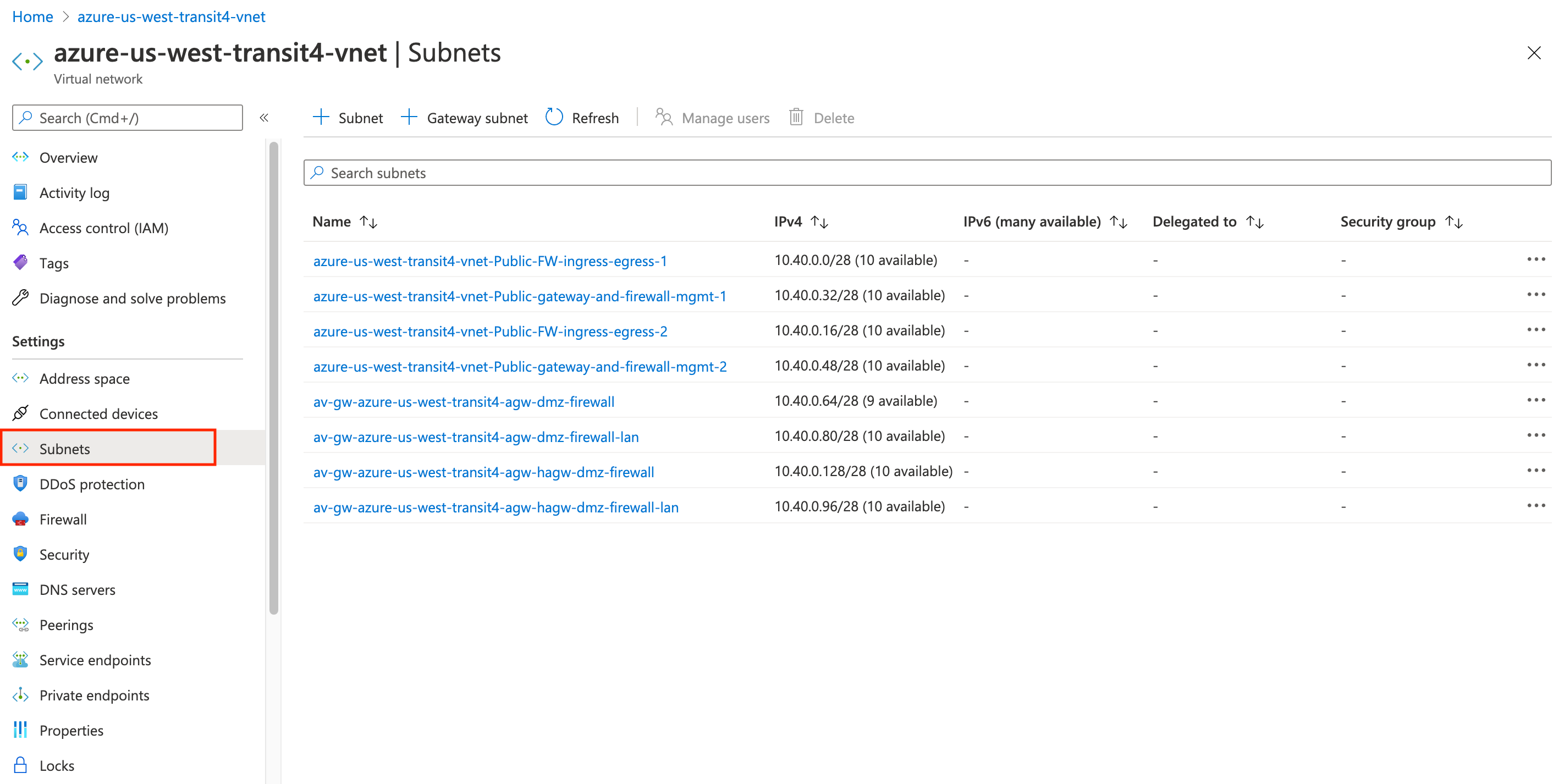
Notice how this structure maps with the topology shown earlier.
Based on the topology, here are the NICs of the devices in the Transit VNet (let's focus on just one of the firewalls - azure-us-west-cp1):
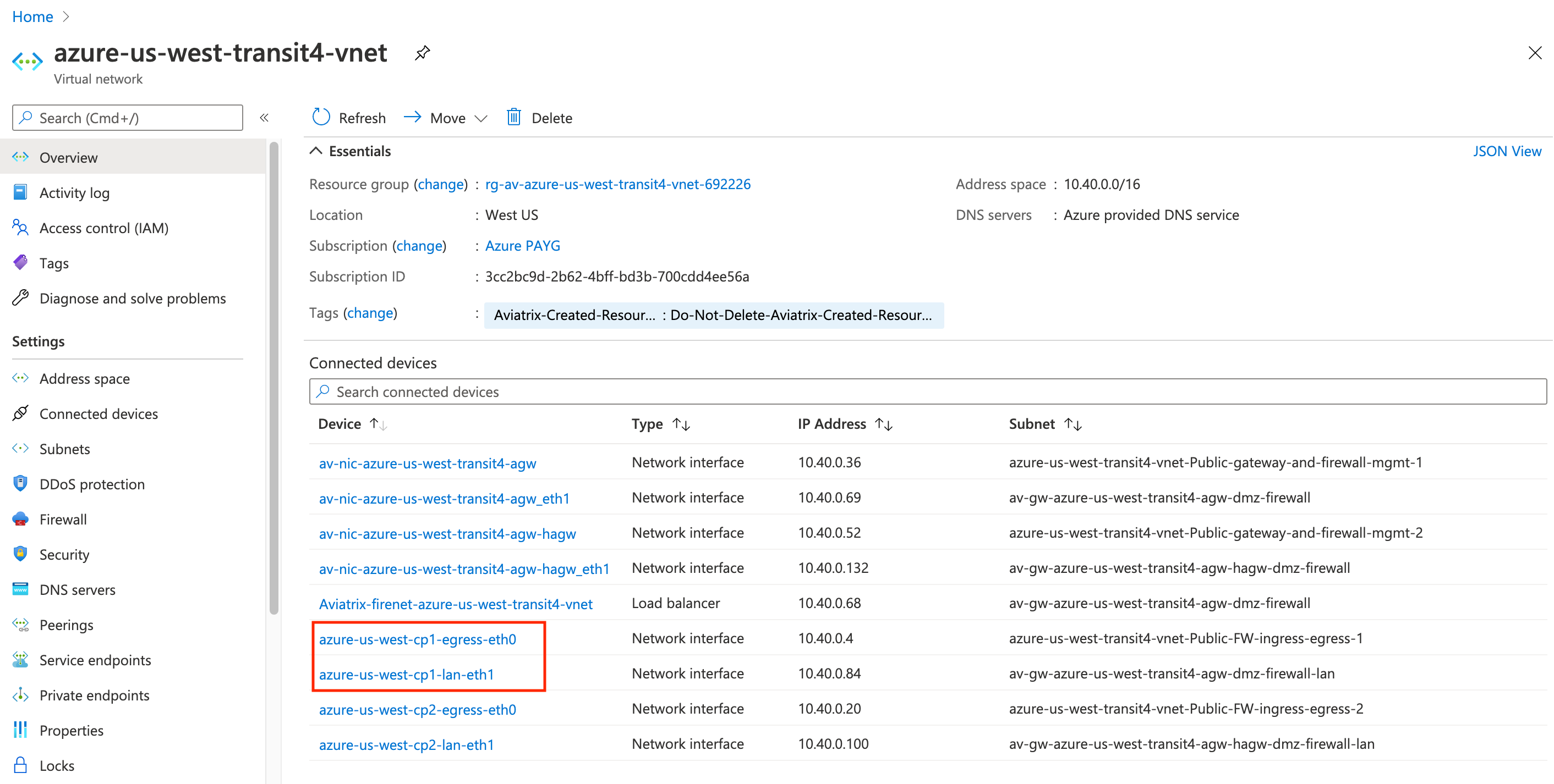
The Controller automatically created those NICs eth0 and eth1, and assigned them to the appropriate subnets.
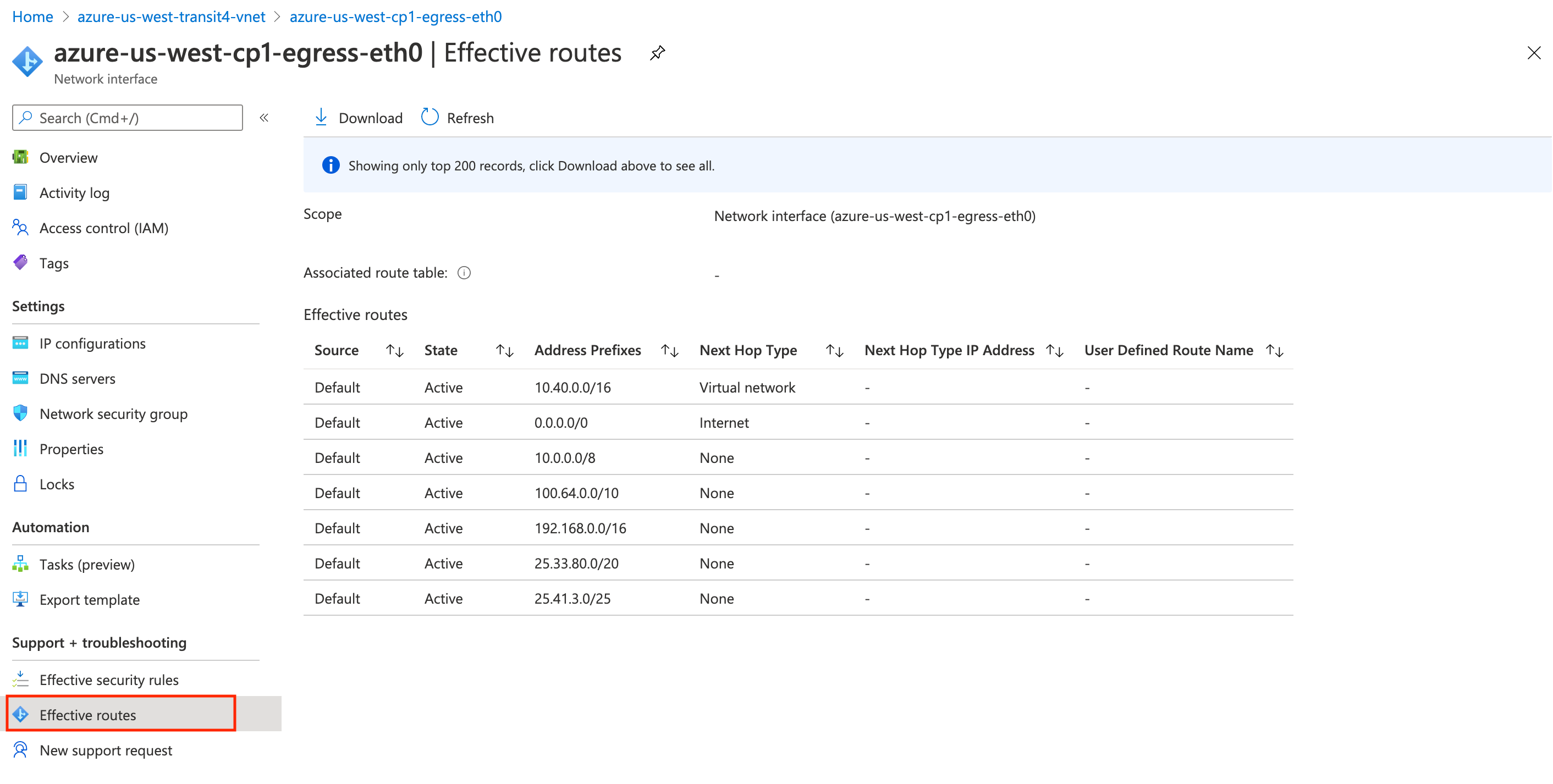
Let's now take a look at the routes that the Controller programmed on these NICs. Here is the route for eth0, which is in the -Public-FW-ingress-egress-1 subnet:
Here is the route for eth1, which is in the -dmz-firewall-lan subnet:
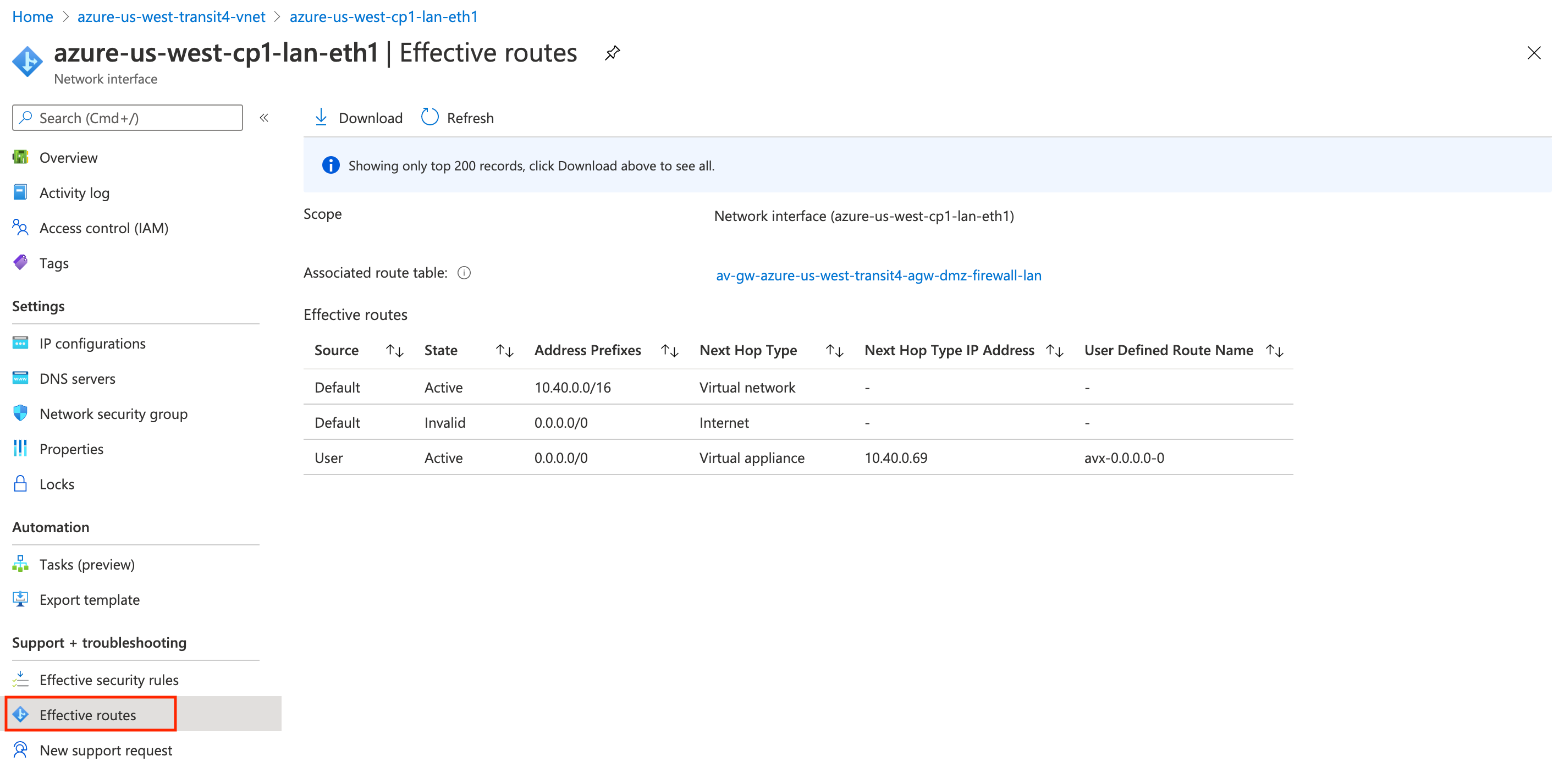
Again, these routes were programmed automatically by the Controller. And that is just the tip of the iceberg.
Packet Walk of East-West Traffic
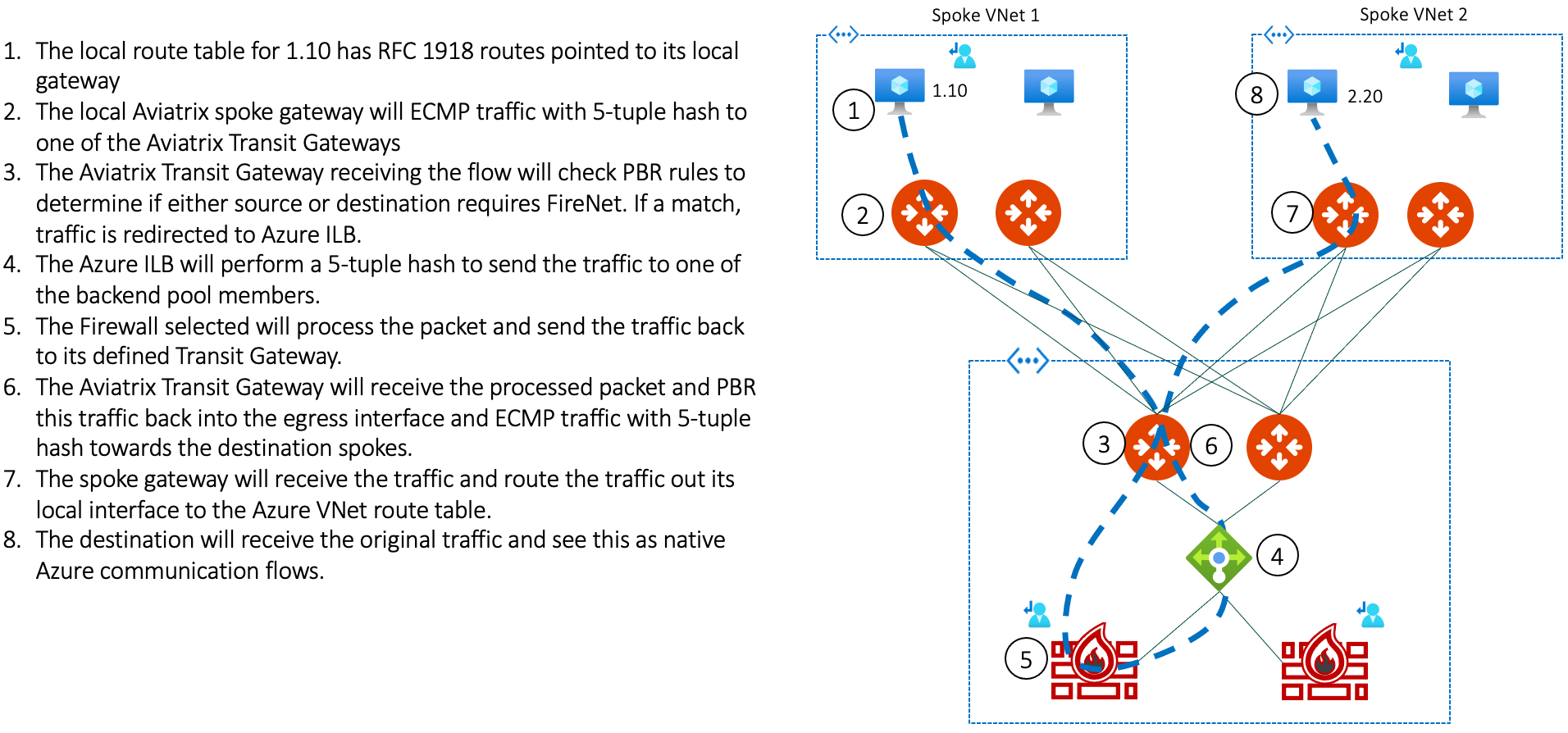
Let's take a look at Host 1.10 communicating with 2.20 with Spoke VNet 1 inspected via FireNet (in this diagram, 2 Aviatrix gateways are in each Spoke VNet):
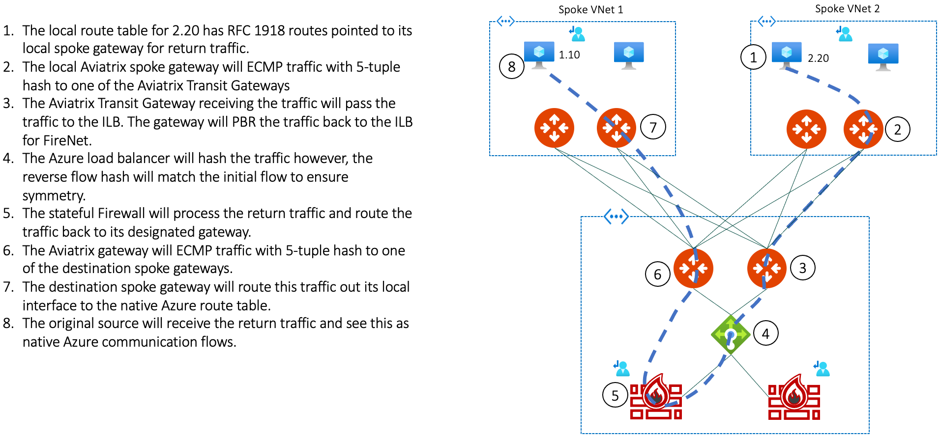
And here is the return traffic from Spoke 2 to Spoke 1:
Verification of East-West Traffic
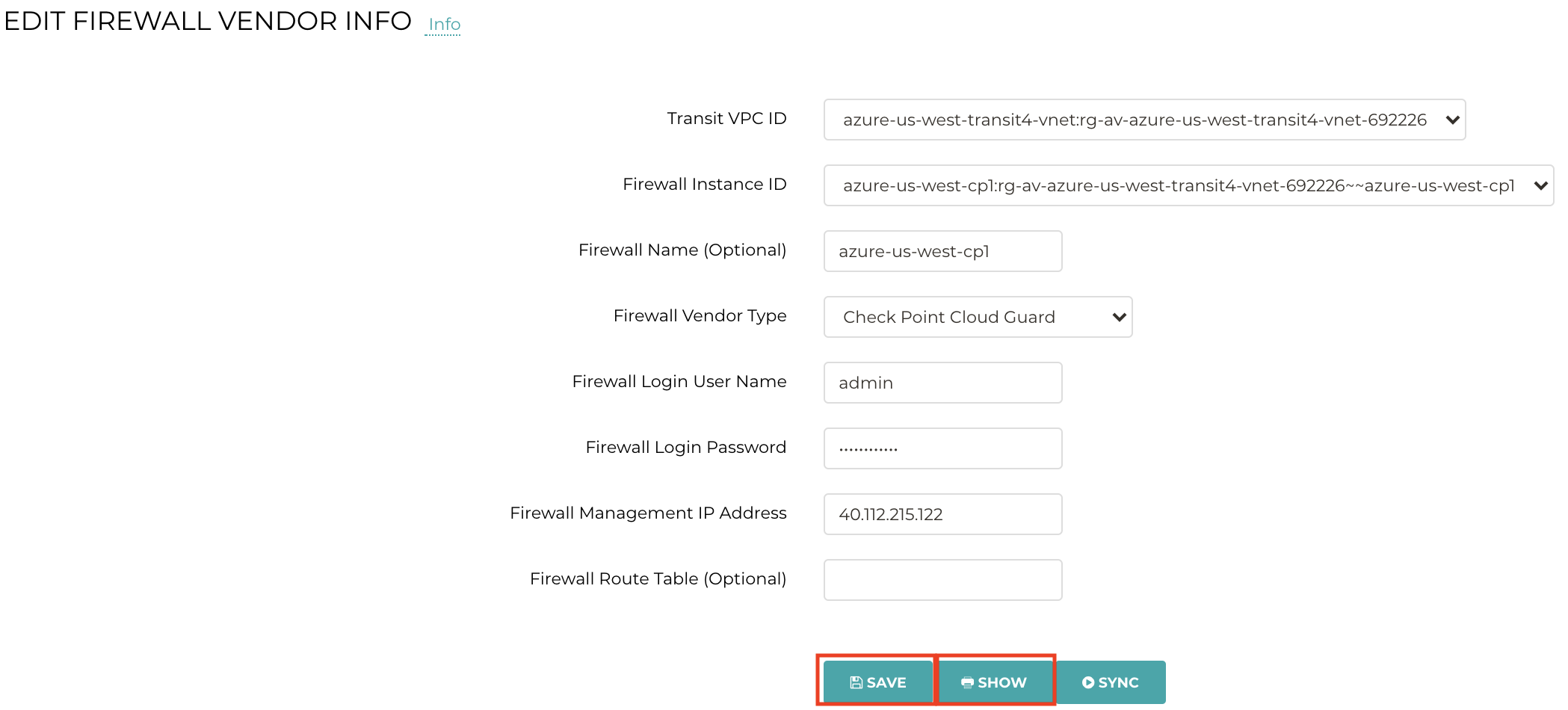
You can also perform vendor integration from the Controller to program RFC 1918 routes into the control plane of the Firewall OS. This is to enable East-West traffic between the Spokes, which are in the RFC 1918 address space.
From the Controller, click “SHOW” to see the RFC 1918 routes that the Controller automatically programmed on the Firewall.
Name: azure-us-west-cp1
Vendor: Check Point Cloud Guard
Public IP: 40.112.215.122
Route Table:
Codes: C - Connected, S - Static, R - RIP, B - BGP (D - Default),
O - OSPF IntraArea (IA - InterArea, E - External, N - NSSA),
A - Aggregate, K - Kernel Remnant, H - Hidden, P - Suppressed,
U - Unreachable, i - Inactive
S               0.0.0.0/0           via 10.40.0.1, eth0, cost 0, age 1039717
S               10.0.0.0/8          via 10.40.0.81, eth1, cost 0, age 1039717
S               168.63.129.16/32    via 10.40.0.81, eth1, cost 0, age 1039717
S               169.254.169.254/32  via 10.40.0.1, eth0, cost 0, age 1039717
S               172.16.0.0/12       via 10.40.0.81, eth1, cost 0, age 1039717
S               192.168.0.0/16      via 10.40.0.81, eth1, cost 0, age 1039717
Verification of Egress Traffic
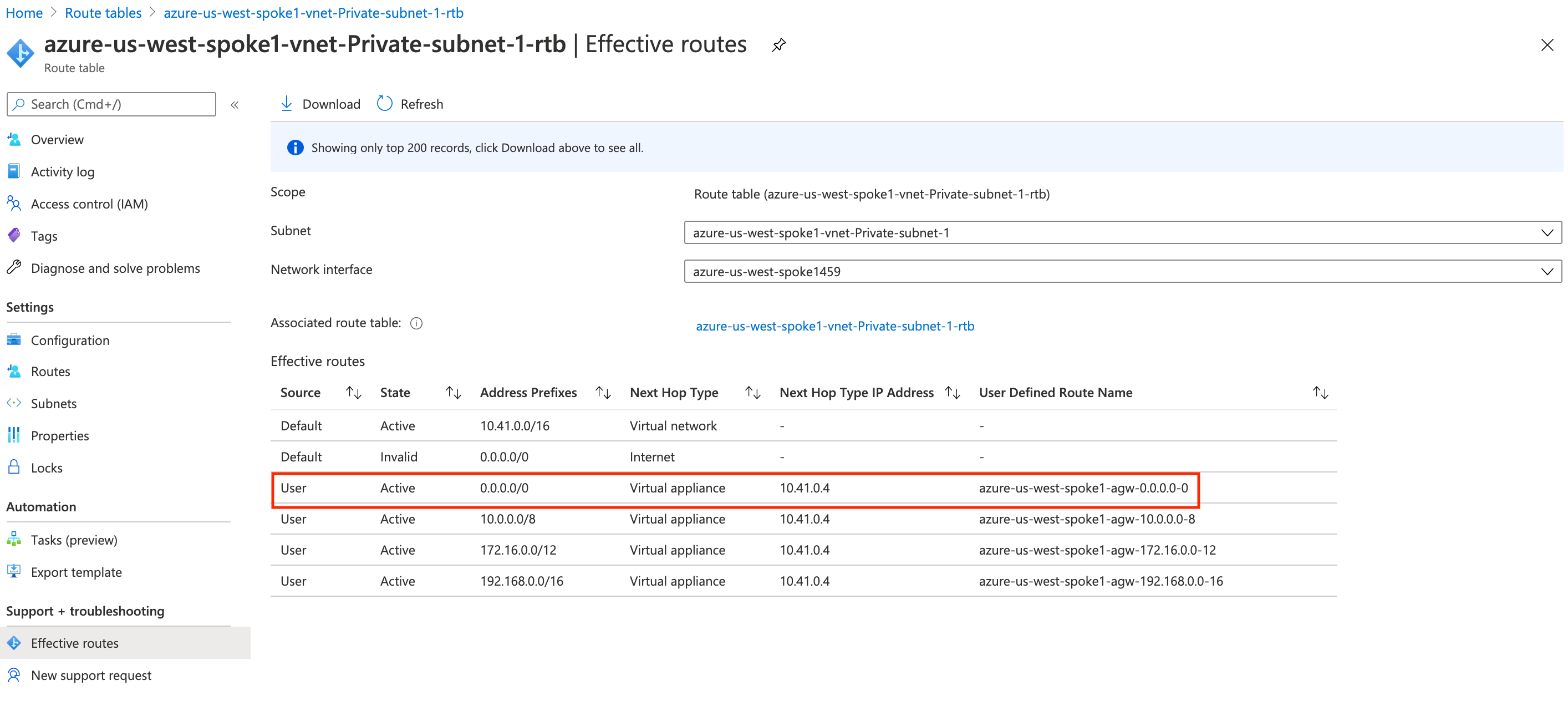
Let's take a look at the route table of the subnet where the spoke gateway is in. On the Azure portal, these routes are programmed:
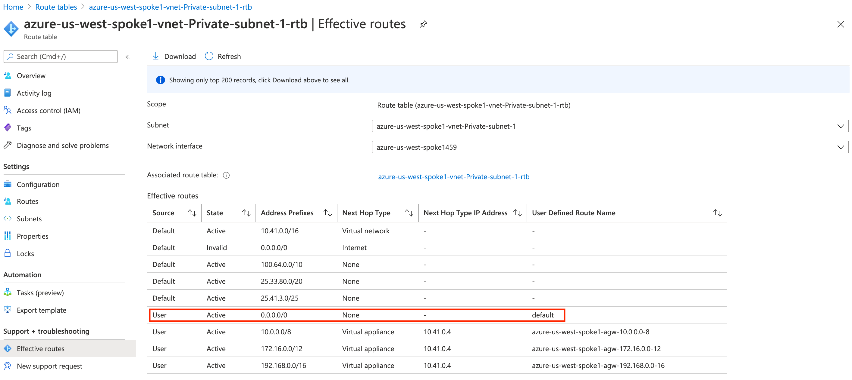
Notice how 0.0.0.0/0 points to the default UDR.
But suppose now we want this Internet-bound traffic (not just the East-West RFC 1918 traffic) to also be inspected by the firewalls. Well, we would simply enable FIREWALL NETWORK > Advanced > Egress through Firewall as shown here.
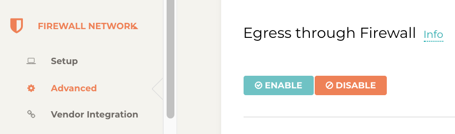
Upon doing so, the Controller programs the 0.0.0.0/0 route in that subnet to the UDR for the spoke gateway as seen here: