

Introduction
When it comes to do a service chaining with Palo Alto Firewall in the Cloud, the Aviatrix FireNet is by far the best enterprise and service provider (SP) grade solution.
There are some customer use-cases when Cloud needs to connect to on-prem physical Palo Alto firewall at some branch or data center location. This article helps customer implement such connectivity back to Aviatrix Global Transit Architecture.
In this article we are using Palo Alto VM-Series as the firwall that is deployed in a VPC to simulate on-prem Palo Alto Firewall. Steps mentioned here should be applicable regardless.
Setup
Following is the customer topology we are using to build this setup
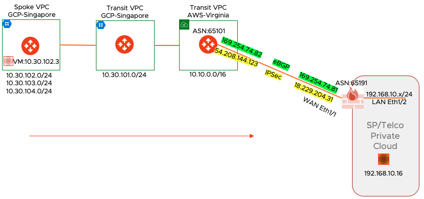
- On the right hand side, the Palo Alto Firewall is in on-prem Telco data center
- WAN is connected to Eth1/1 and LAN to Eth1/2
- LAN side subnet 192.168.10.0/24 has a destination test machine with 192.168.10.16 IP
- The WAN side is connected to Aviatrix Transit GW in Virgnia VPC
- Virginia Transit is connected to Aviatrix transit in GCP
- There is a Singapore spoke VPC in GCP where we have a source VM with the IP 10.30.102.3.
- This Singapore spoke VPC is also advertising other subnets all the way to On-Prem Data center
Setting Up The Aviatrix Global Transit Network
This document assumes that customer has already setup the Aviatrix global transit network as shown in the diagram. The only thing left is the IPSec VPN connection from AWS-Virginia Transit to On-prem Palo Alto Firewall
Aviatrix Transit Connection to On-Prem
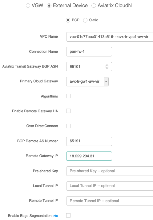
By using simple point and click in Aviatrix Controller, we build the connection policy first as shown in the diagram below (Transit Network --> Setup --> External Device --> BGP)
Download Remote Device Configuration
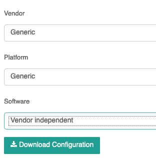
Site2Cloud section in the controller provides the configuration for the remote device which in our case is Palo Alto Firewall.
Aviatrix Site2Cloud configuration.
This connection has two IPsec tunnels between the customer gateway and Aviatrix gateways in the cloud.
Tunnel #1 is the primary tunnel. The customer gateway should be configured in such a way that it should
switch over to tunnel #2 when tunnel #1 fails.
Tunnel #1 (Primary)
================================================================================
#1: Internet Key Exchange Configuration
Configure the IKE SA as follows
- Version : 1
- Authentication Method : Pre-Shared Key
- Pre-Shared Key : 123shahzad123
- Authentication Algorithm : SHA-256
- Encryption Algorithm : AES-256-CBC
- Lifetime : 28800 seconds
- Phase 1 Negotiation Mode : main
- Perfect Forward Secrecy : Diffie-Hellman Group 14
- DPD threshold : 10 seconds
- DPD retry interval : 3 seconds
- DPD retry count : 3
#2: IPSec Configuration
Configure the IPSec SA as follows:
- Protocol : esp
- Authentication Algorithm : HMAC-SHA-256
- Encryption Algorithm : AES-256-CBC
- Lifetime : 3600
- Mode : tunnel
- Perfect Forward Secrecy : Diffie-Hellman Group 14
IPSec ESP (Encapsulating Security Payload) inserts additional
headers to transmit packets. These headers require additional space,
which reduces the amount of space available to transmit application data.
To limit the impact of this behavior, we recommend the following
configuration on your Customer Gateway:
- TCP MSS Adjustment : 1387 bytes
- Clear Don't Fragment Bit : enabled
- Fragmentation : Before encryption
#3: Tunnel Interface Configuration
Your Customer Gateway must be configured with a tunnel interface that is
associated with the IPSec tunnel. Traffic that should go through the tunnel
should be specified by following your gateway's configuration guide, using the
information below.
Gateway IP addresses:
- Customer Gateway : 18.229.204.31
- Aviatrix Gateway Public IP : 54.208.144.123
- Aviatrix Gateway Private IP : 10.10.0.29
Subnets:
- Customer Network(s) : N/A for transit network
- Cloud Networks(s) : N/A for transit network
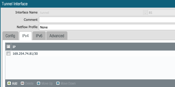
Tunnel Inside IP addresses:
- Customer Gateway : 169.254.74.81/30
- Aviatrix Gateway : 169.254.74.82/30
Configure your tunnel to fragment at the optimal size:
- Tunnel interface MTU : 1436 bytes
#4. Border Gateway Protocol (BGP) Configuration:
The Border Gateway Protocol (BGPv4) is used to exchange routes from the VPC to on-prem
network. Each BGP router has an Autonomous System Number (ASN).
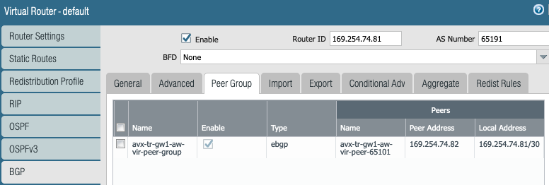
BGP Configuration:
- BGP Mode : true
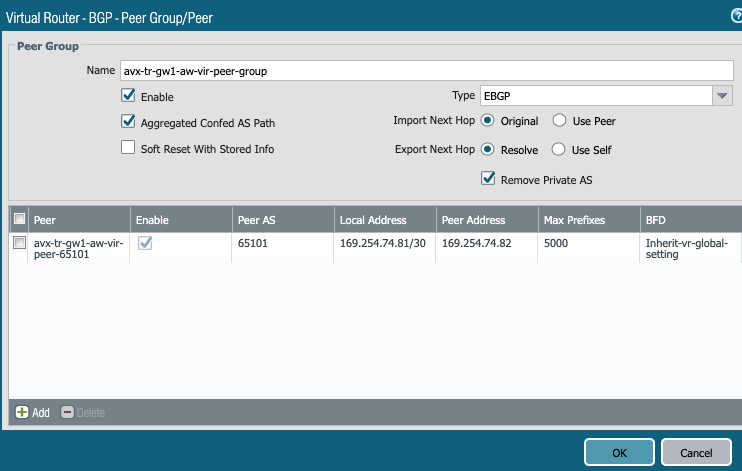
- Customer Gateway ASN : 65191
- Aviatrix Gateway ASN : 65101
Configure BGP to receive routes from on-prem network. Aviatrix Transit gateway will announce
prefixes to your on-prem gateway based upon the spokes you have attachedPalo Alto VM-Series Firewall Configuration
Rest of the article will show various screen shots to build the IPSec tunnel and BGP config.
It is important that, first we must build the IPSec and then BGP will be running on top of that tunnel
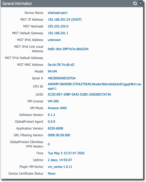
Following screen shows basic information about VM-Series iteself. Notice the PAN version we are using for this deployment. If you are using a different version, your screens might look bit different.
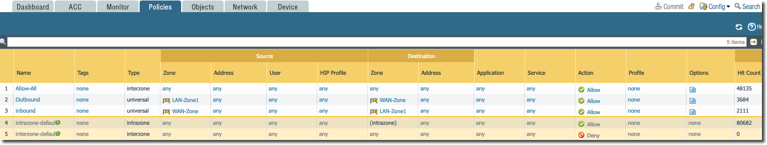
Firewall Security Policy
Following screen grab shows the firewall security policies we have configured. For the purpose of this deployment, we have allow-all policy for East-West and Ingress/Egress traffic. This must be changed and must match to your enterprise policy requirement.
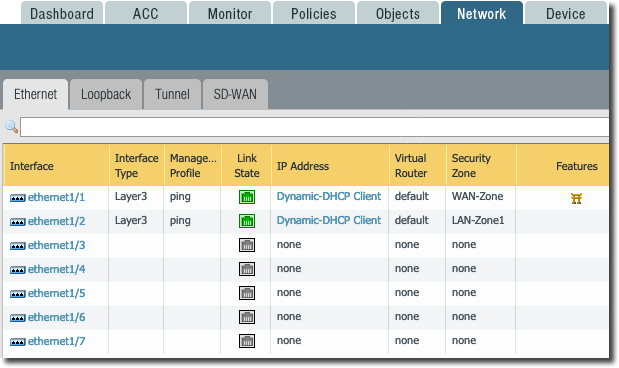
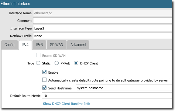
Ethernet Interface Configuration
Following screen shows various interfaces. In PAN VM-Series interface
- eth0 --> mgmt traffic
- eth1/1 --> WAN/INTERNET/Egress traffic
- eth 1/2 --> LAN/East-West Traffic
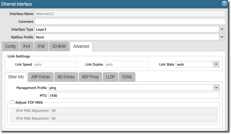
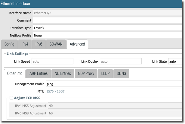
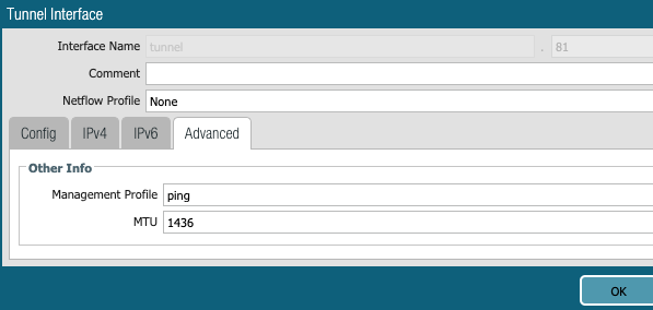
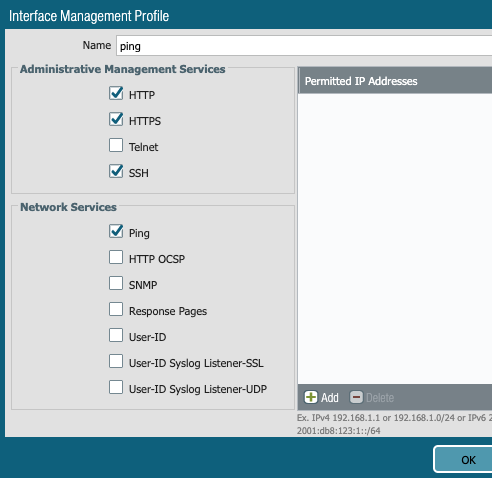
In the following screen, notice the "ping management profile" to allow ping on the LAN side. Also notice the MTU changed to 1436. This is to allow tunnel to build, stop fragmentation and to accommodate IPSec header overhead.
IPSec Related Configuration
There are five major step involved here
1- Create IPSec tunnel interface
2- Define IPSec Crypto
3- Define IKE Crypto
4- Build IKE Gateway config
5- Create IPSec tunnel with IKE Gateway and IPSec Crypto
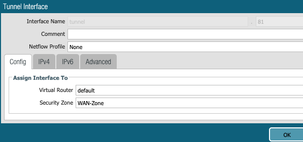
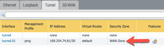
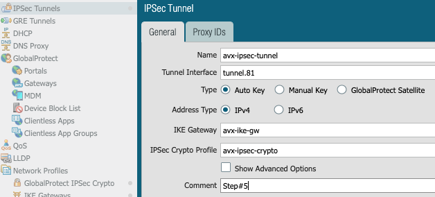
1- Create IPSec Tunnel Interface
Create IPSec tunnel.81 to connect to Aviatrix Transit Gateway. We need to assign it to WAN-Zone because this is where it needs to talk to Aviatrix Transit GW public IP.
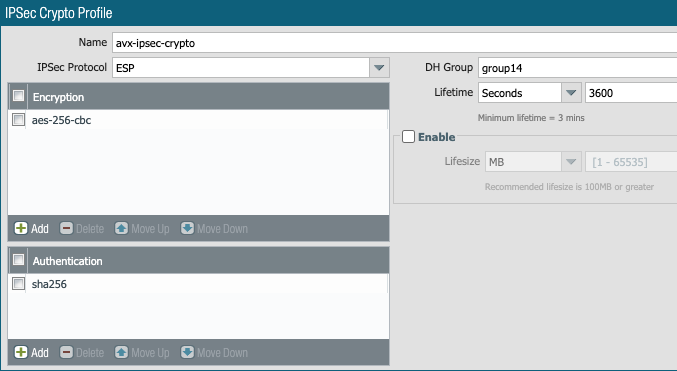
2- Define IPSec Crypto
Under Network Profile Section configure following (based on the text file we got from Aviatrix Controller)
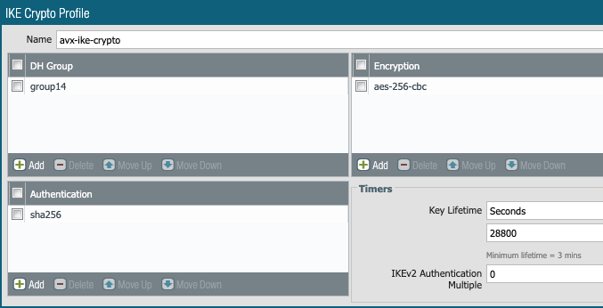
3- Define IKE Crypto
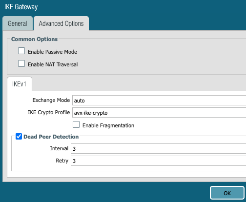
4- Build IKE Gateway config
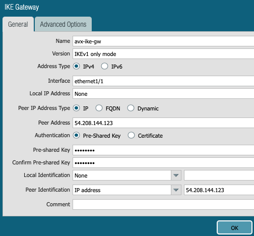
Add a new IPSec tunnel and tunnel interface. Do not touch Proxy IDs

5- Create IPSec tunnel with IKE Gateway and IPSec Crypto

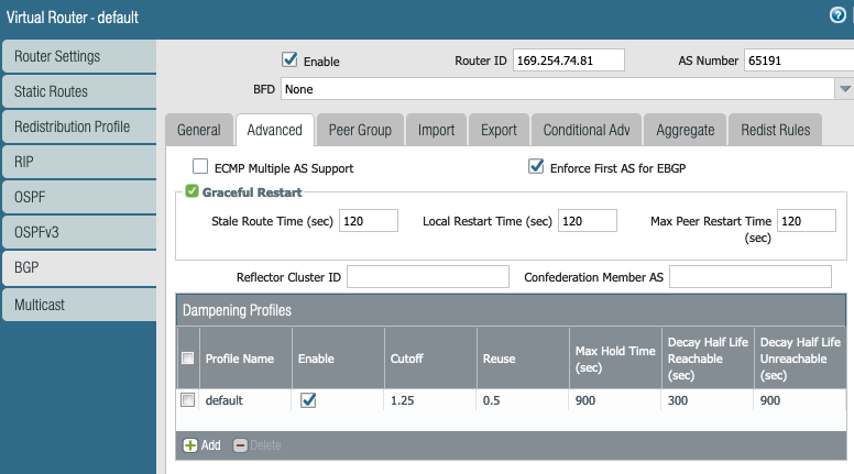
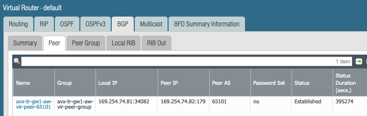
BGP Routing Configuration
Now IPSec is built and tunnel is UP. At this stage we can configure routing and BGP to run on top of IPSec tunnel.
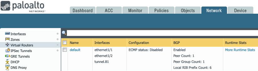
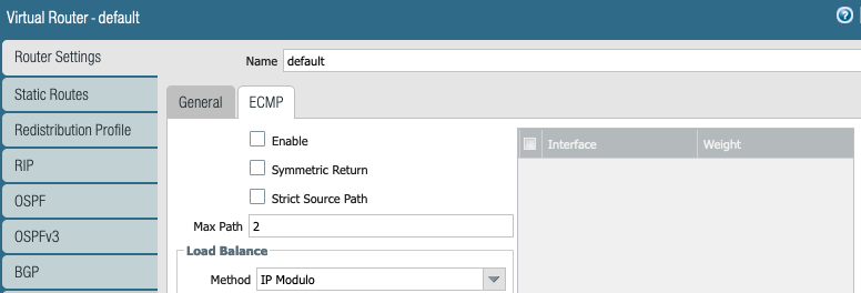
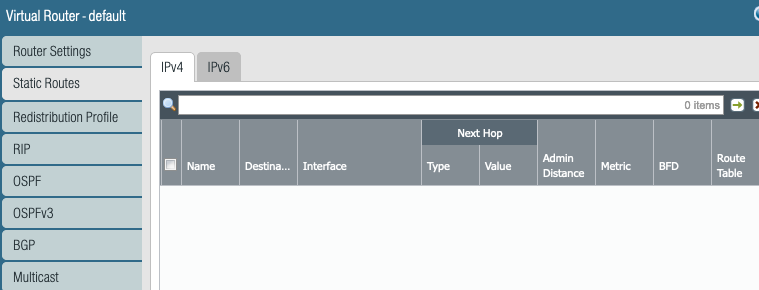
Routing is configured under "Virtual Router" section.
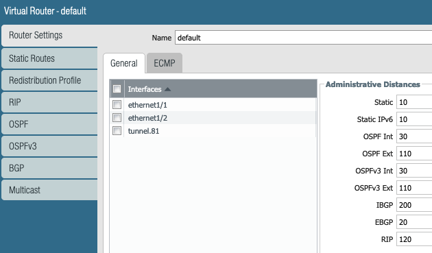
Since we are using eBGP, we have not configured any static routes.
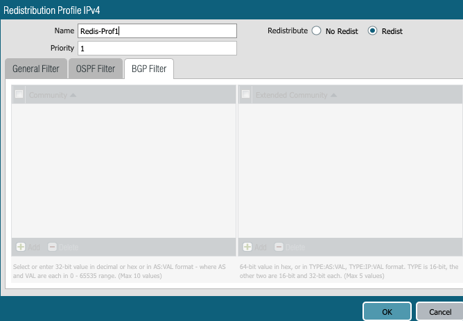
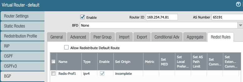
Redistribution profile is needed to advertise the connected LAB subnets to remote (Aviatrix Transit GW) side.
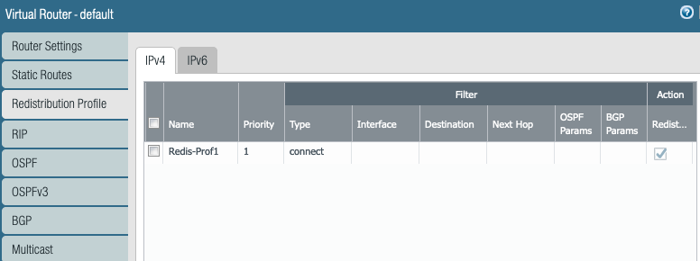
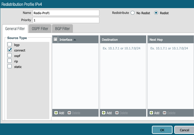
Public Cloud protocol is BGP. That is it. No need to worry about RIP and OSPF. Both of them are RIP in Public Cloud :-)
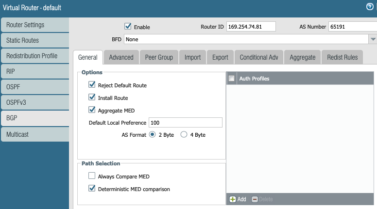
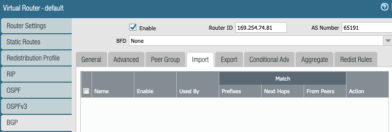
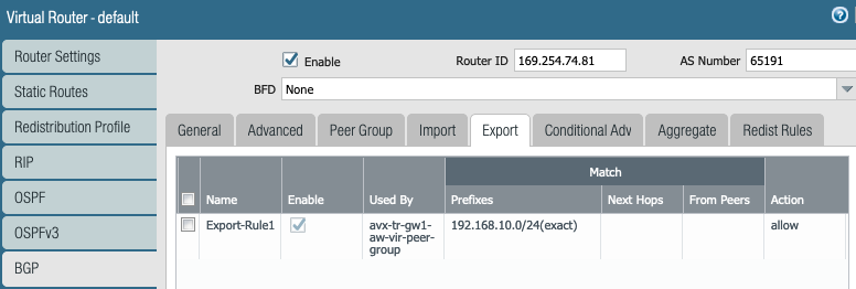
Export the local LAN subnets in BGP towards Aviatrix Transit GW.

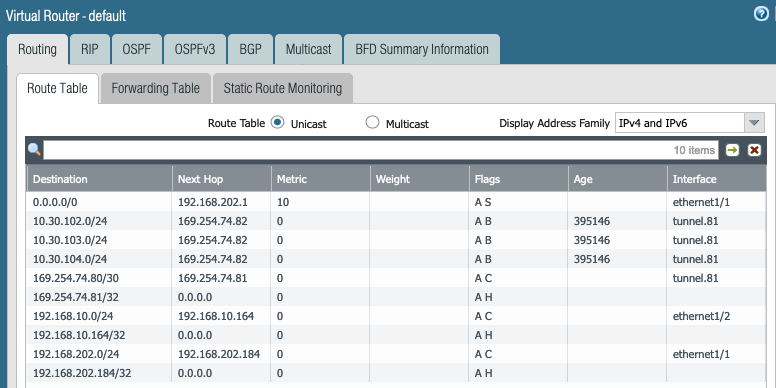
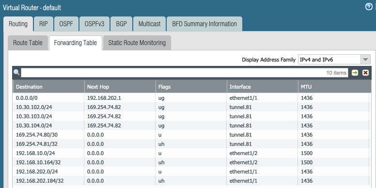
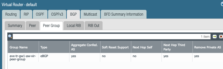
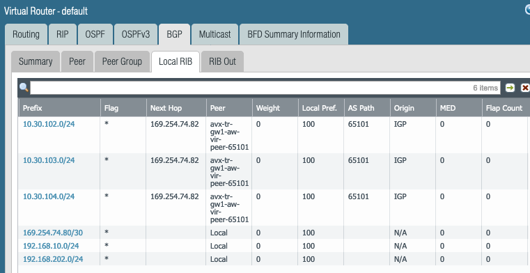
Routing Runtime Stats
More Runtime Stats shows following. Look at the 10.30.102.0/24, 10.30.103.0/24 and 10.30.104.0/24 routes learned from Aviatrix Transit GW via BGP.

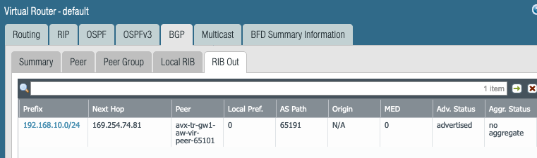
Look at the RIB out due to the BGP export policy.
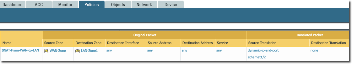
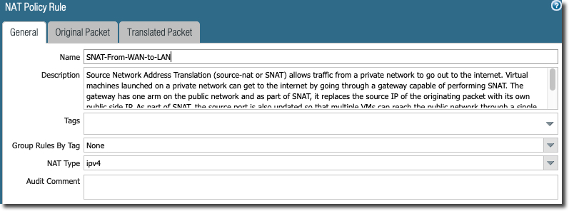
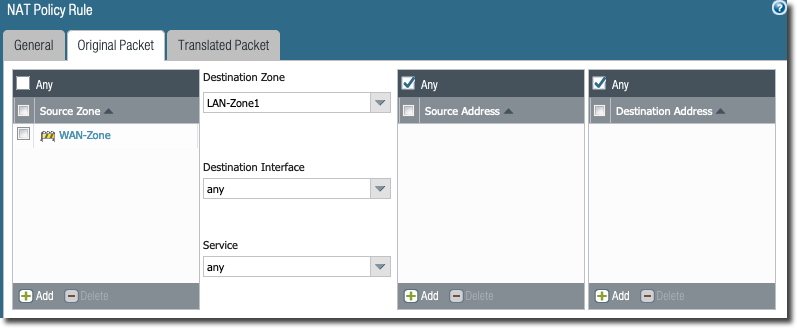
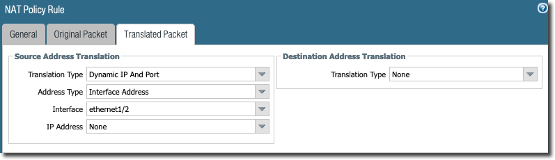
NAT Policy
Reference
https://docs.aviatrix.com/HowTos/Transit_ExternalDevice_PaloAlto.html